Custom Fiberglass Mold Design and Manufacturing for Composite Parts
Custom FRP (fiber-reinforced polymer) molds are used to manufacture composite components in applications where part geometry, surface finish, dimensional requirements, and production methods determine the tooling design.
We develop mold solutions based on customer drawings, 3D CAD models, material requirements, and the intended molding process. Depending on the part design and project requirements, tooling may be designed for processes such as hand lay-up, vacuum infusion, resin transfer molding (RTM), or compression molding.
Mold construction can be evaluated according to the required tool surface, backing structure, operating temperature, vacuum conditions, clamping loads, and expected production volume.
To help determine a suitable mold configuration, please provide your part drawings or 3D model, the intended molding process, resin system, dimensional requirements, and expected production quantity.
-
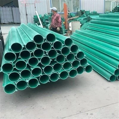
![FRP Pipe Mold]() FRP Pipe MoldHere is FRP Pipe Mold, engineered for filament winding and pultrusion processes. This precision fiberglass pipe mould that gives you smooth surfaces, consistent wall thickness, and long service life
-
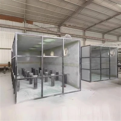
![FRP Tank Mold]() FRP Tank MoldOur FRP Tank Mold, designed for winding and compression molding of FRP storage tanks. This precision Fiberglass tank mould delivers smooth inner walls, uniform thickness, and reliable sealing for
-
![FRP Cable Pipe Mold]() FRP Cable Pipe MoldOur FRP Cable Pipe Mold, designed for winding, pultrusion, and compression molding of FRP cable protection pipes. This precision Fiberglass cable duct mould, it delivers smooth inner walls, accurate
-
![Cantilever Beam Tank Mould]() Cantilever Beam Tank MouldOur Cantilever beam tank mould, designed for winding and compression molding of FRP tanks with integrated cantilever structures. This specialized fiberglass cantilever tank mould, it ensures uniform
-
![Fiberglass Field Ditch Mould]() Fiberglass Field Ditch MouldOur Fiberglass field ditch mould. It's designed for casting concrete field ditches in agricultural land. This mould resists wet soil, chemicals, and outdoor weather , and it delivers smooth ditch
-
![FRP Grating Mold]() FRP Grating MoldOur FRP Grating Mold. It's made for casting FRP gratings with exact grid patterns. This strong fiberglass grating mould fights corrosion and wears out slowly , and it gives even grids for chemical
-
![FRP Septic Tank Mold]() FRP Septic Tank MoldHere is FRP Septic Tank Mold, designed for one-piece or split casting of FRP septic tanks. As a durable fiberglass septic tank mould, it resists acid and alkali attack, seals tightly, and gives you
-
![FRP Inspection Well Mold]() FRP Inspection Well MoldOur FRP Inspection Well Mold, designed for casting FRP inspection chambers for municipal and residential use. As a durable fiberglass inspection well mould, it resists wet soil, acid/alkali, and
-
![FRP Drainage Ditch Cover Mold]() FRP Drainage Ditch Cover MoldOur FRP Drainage Ditch Cover Mold, designed for casting FRP covers for U-shaped and rectangular drainage ditches. As a strong fiberglass drainage ditch cover mould, it resists wet outdoor conditions,
-
![FRP U-Shaped Drainage Ditch Mold]() FRP U-Shaped Drainage Ditch MoldHere is the FRP U-Shaped Drainage Ditch Mold. It is made for casting U-shaped drainage ditches. It is a strong fiberglass U-shaped trench mould. So it fights wet ground, acid/alkali soil, sewage, and


Key Features
Custom Tooling Design: Mold geometry and tooling layout are developed around the part design, trim lines, draft requirements, molding process, and demolding method. CAD data can be reviewed before manufacturing to identify design details that may affect tooling production.
Mold Material Options: The tooling material system can be selected according to the required surface finish, operating temperature, production volume, and compatibility with the specified resin system. Depending on the design, options may include tooling gelcoat systems, epoxy or vinyl ester systems, and suitable tooling-board materials.
Structural Support Design: A backing structure may be incorporated where required by the mold size, geometry, vacuum conditions, clamping loads, or handling requirements. Steel or aluminum support structures should be selected and designed according to the actual loading and operating conditions.
Surface Finish Requirements: The mold surface is prepared according to the specified finish and the requirements of the molded part. Surface preparation and inspection criteria should be agreed upon before production, particularly for visible surfaces and parts with demanding cosmetic requirements.
Optional Temperature Control: Where required by the molding process, temperature-control provisions may be considered as part of the tooling design. The heating or cooling method, operating temperature, and temperature distribution requirements should be confirmed for each project.
Technical Specifications
|
Technical Parameter |
Selection or Specification Basis |
|
Mold dimensions |
Based on the part geometry, tooling layout, and available manufacturing envelope |
|
Tooling material system |
Selected according to the molding process, resin system, temperature, and production requirements |
|
Mold surface finish |
Defined by the required finish of the molded part and agreed inspection criteria |
|
Dimensional tolerance |
Specified for critical dimensions, contours, interfaces, and trim lines |
|
Backing structure |
Designed according to mold size, handling requirements, and operating loads |
|
Operating temperature |
Confirmed against the tooling material system and curing process |
|
Vacuum requirements |
Defined according to the molding process and specified operating conditions |
|
Compatible resin systems |
Confirmed for the selected tooling materials and intended process |
|
Temperature-control system |
Optional, subject to project requirements and design feasibility |
|
Inspection method |
Selected according to the required tolerances and inspection scope |
Dimensional Inspection and Verification
Where required and available, dimensional inspection may include comparison of measured tooling geometry against the approved CAD model. The inspection method, measurement locations, tolerance criteria, and report format should be agreed upon before manufacturing.
Surface finish, thermal performance, vacuum integrity, and structural deflection require their own applicable acceptance criteria. A dimensional inspection report alone does not establish compliance with all of these requirements.

Manufacturing Capabilities
CAD/CAM Engineering
Customer drawings and 3D CAD files can be used as the basis for tooling design and manufacturing planning. Engineering review includes evaluation of part geometry, trim lines, draft angles, demolding requirements, tooling layouts, and material shrinkage allowances. Commonly supported 3D file formats include STEP and IGES.
Master Pattern and Tool Surface Preparation
Depending on the tooling design, the manufacturing process incorporates pattern preparation, precision machining, surface finishing, and mold-surface preparation based on the selected material and required surface quality.
Mold Fabrication and Reinforcement
Mold fabrication methods are selected according to mold construction and service conditions. Structural backing frames (steel or aluminum) are integrated with defined geometry, joining methods, lifting provisions, and mounting interfaces.
Assembly and Final Preparation
Before delivery, agreed inspection and preparation activities are completed, including dimensional checks, surface inspection, interface verification, and review of operating or handling features.
Quality Control and Inspection
Quality requirements for custom FRP molds are established around the approved design, specified operating conditions, and acceptance criteria. Depending on project scope, the inspection plan covers:
Dimensional Inspection: Verification of specified dimensions and contours against approved drawings or CAD data.
Surface Inspection: Examination of the mold surface for visible defects against agreed acceptance criteria.
Structural Review: Assessment of the backing structure and support arrangements against defined design loads, where required.
Material Traceability: Review of available material identification and supplier documentation for specified components.
Functional Verification: Inspection or testing of agreed features, such as interfaces, lifting points, vacuum connections, or temperature-control provisions, where applicable.

Applications
Custom FRP molds are developed for composite manufacturing applications when part geometry, molding process, material system, and tooling design are compatible.
Wind Energy
Potential tooling applications include composite covers, spinner components, and tooling for wind turbine blade production.
Marine
Molds designed for composite hulls, decks, and superstructure components for commercial or recreational vessels.
Automotive and Commercial Transport
Potential applications include composite body panels, fairings, roof components, and shaped transport parts.
Industrial and Infrastructure
Custom tooling for selected composite panels, tank components, rail-vehicle interior parts, and industrial FRP products.
Frequently Asked Questions
We're well-known as one of the leading FRP mold manufacturers and suppliers in China, featured by quality products and good service. Please rest assured to buy customized FRP mold at competitive price from our factory. Contact us for more details.
FRP Process Pipe Mould, FRP U Shaped Drainage Ditch Mold, fiberglass drainage ditch cover mouldPopular Products